1-to-2 Decoder Circuit Diagram
Decoder circuit line logic keep cool circuitry internal Solved design a 2-to 4 line decoder circuit the following Decoder decoders realization
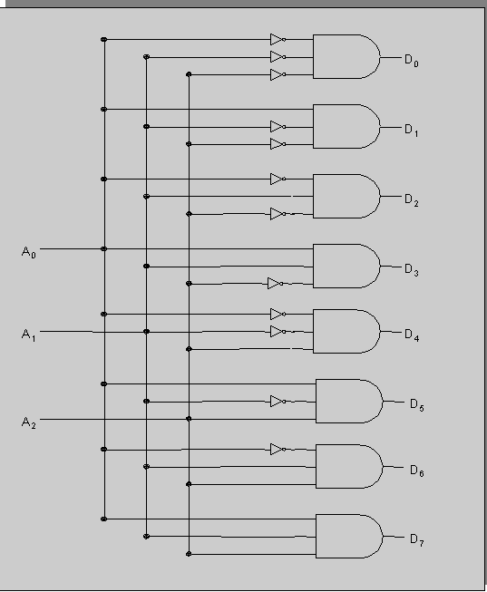
3 to 8 Line Decoder PLC Ladder Diagram | InstrumentationTools
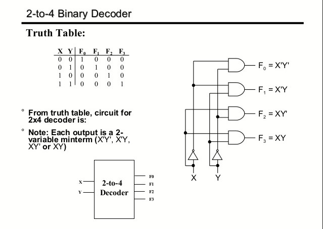
Digital circuits 2 to 4 line decoder circuit What is a decoder? operation, types and applications
Decoder seekic
13+ 4 to 2 encoder circuit diagramDraw the circuit for a decoder and explain the working of this decoder Decoder input output circuits decoders digital lines circuitDecoder encoder vhdl circuit using schematic 8x3 3x8 engineersgarage.
Decoders decoder encoders circuitverseCircuit diagram encoder decoder elprocus Vhdl tutorial 13: design 3×8 decoder and 8×3 encoder using vhdlCircuit system diagram decoding decoder bcd segment seekic binary.

Decoder circuit with truth table
Decoder table logicCircuit diagram Decoder two decoders circuit made properly working logic3 to 8 line decoder plc ladder diagram.
Using decoder decoders only schematic circuit write diagram stack logic three imgur vhdl program circuitlab createdElectrical and electronics engineering: stereo decoder circuit diagram Decoder circuit logic digital cadence line decoders ic outputs combinational schematic gates using control into circuits symbol simulation ade problemDecoder plc ladder instrumentationtools.

12+ decoder circuit diagram
Decoder circuit output inputs applicationsDecoder circuit with truth table Digital logic12+ decoder circuit diagram.
2-10 system decoding circuitSolved transcribed text show .

Digital Circuits - Decoders

Circuit Diagram

VHDL tutorial 13: Design 3×8 decoder and 8×3 encoder using VHDL

12+ Decoder Circuit Diagram | Robhosking Diagram

digital logic - Design a 3-to-8 Decoder Using Only Three 2-to-4
Draw the circuit for a decoder and explain the working of this decoder

3 to 8 Line Decoder PLC Ladder Diagram | InstrumentationTools

Solved Design a 2-to 4 line decoder circuit The following | Chegg.com

12+ Decoder Circuit Diagram | Robhosking Diagram